Error check using CRC Peripheral | STM32F4 | CRC | CMSIS
Cyclic Redundancy Check
Cyclic Redundancy Check, or CRC in short is an error-detecting code used to check data integrity in digital data. It involves executing the Modulo 2 Arithmetic division of a Message polynomial with a Generator polynomial and then appending the remainder of the division to the tail of the Message polynomial to get a complete Data frame for transmission. This is the process carried out on the Transmitter side. Then, on the Receiver side, another Modulo 2 Arithmetic Division is carried out with the same Generator polynomial to check for a 'zero' remainder, and if not found, an error has occurred. This is the basic layout of Cyclic Redundancy Check. If you want to get a better understanding of the process, check out Jacob Schrum's video on CRC or Ben Eater's explanation on CRC working. If you are enthusiastic about diving deep into Checksums and CRC, check out the blogs maintained by Philip Koopman at Carnegie Mellon University. He has a lot to share.

CRC Peripheral and Registers
The STM32F401 has the Cyclic Redundancy Check calculation unit as a peripheral. It has a fixed generator polynomial, the CRC-32 implementation. It is widely used in error correction in Ethernet. 0x04C11DB7 is the CRC-32 generator polynomial.

The CRC registers that are available to us are:
- CRC Data Register (CRC_DR)
- CRC Independent Data Register (CRC_IDR)
- CRC Control Register (CRC_CR)
Among these, we won't be using the CRC_IDR register.
Configuring and Application of CRC Peripheral
The only configuration required for the CRC peripheral is Enabling the Clock to the CRC Calculation Unit and Resetting the Peripheral. CRC can calculated for a single 32-bit word or a block of 32-bit words. For a single 32-bit word, the CRC code is stored in the CRC_DR register after writing to it. But for a block of 32-bit words, the CRC code is stored in the CRC_DR register after all the words have been written to the CRC_DR. This read will give us the CRC code for a block of data. In application, we need to append the CRC Code that we receive from the Data Register to the end of the Message Data as a Frame Check Sequence (FCS), so that the receiver can parse the FCS to check for data integrity. But the CRC calculation unit doesn't do these, the programmer must do it themselves. It's easy if you want it.
Walkthrough
Function Declarations

Declare Function Headers for Initializing and De-Initializing the CRC calculation unit. Also, declare function headers for calculating the CRC code for a single word and a block of words. In addition to that, declare the necessary functions for configuring the VCOM port as the serial terminal.
CRC Initialization
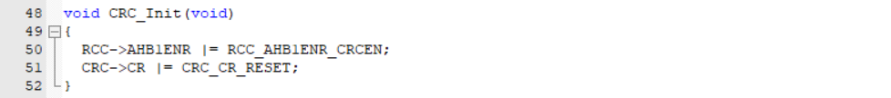
The CRC peripheral is attached to the AHB1 Bus. Hence, to activate it we have to enable the Clock to the CRC peripheral by setting the CRCEN bit in the RCC_AHB1ENR register. Then, Reset the CRC unit by setting the RESET bit in the CRC_CR register.
CRC De-Initialization

When the CRC peripheral is no longer needed, switch off the Clock to the CRC calculation unit by resetting the CRCEN bit in the RCC_AHB1ENR register.
CRC Code for 32-bit word

For generating the CRC code for a single 32-bit word, write the Data, for which we have to generate the checksum, to the CRC_DR register. Then, return the value from CRC_DR as the generated CRC code. But, if you look at the above implementation, shouldn't we wait for the CRC unit to complete the algorithm? The CRC unit halts any access to the Data register until the current calculation is completed. But why are we resetting the CRC each time we generate a CRC code? The CRC peripheral can create a combination of the previous CRC value and the new CRC value for each write operation into the data register.
CRC Code for Block of 32-bit words

For a block of 32-bit words, we specify the starting address and the length of the block. Then, the CRC unit is reset by setting the RESET bit in the CRC_CR register. From there, the block of data is written to the CRC_DR continuously till the end of the block. Finally, the CRC code is returned. Here, a CRC code is generated for a block of code, for example, 512 bytes. Then, this CRC code is appended to the end of the 512 bytes of data as a Frame Check Sequence during transmission or storage.
Generating CRC Code for Dummy Data

Create a character buffer to store the strings that we have to print on the serial terminal. Create a dummy data of 32-bit array. Initialize the UART and CRC peripherals. Call the CRC_Word() function for the testData[0] word and print it to the serial terminal. Then, call the CRC_Block() for the testData[] block and print it to the serial terminal.
If you are enthusiastic enough, you could create a function that takes the message data as an argument to Generate the CRC code and append it to the end of message for transmission. That's all.


