Encrypting using AES Hardware Accelerator | STM32L4 | AES | CMSIS
Advanced Encryption Standard AES-128/256
What is the AES Hardware Accelerator? The AES hardware accelerator (AES) on the STM32L4S5ZI microcontroller encrypts or decrypts data, using an algorithm and implementation fully compliant with the advanced encryption standard (AES). The peripheral supports CTR (Counter Mode), GCM (Galois Counter Mode), GMAC (Galois Message Authentication Code), CCM (Counter with CBC-MAC), ECB (Electronic Codebook), and CBC (Cipher Block Chaining) chaining modes for key sizes of 128 or 256 bits.
The AES Hardware Accelerator contains a 256-bit register for storing the Cryptographic Key (8 * 32-bit registers) and a 128-bit register for storing the Initialization Vector (4 * 32-bit registers). It also has a 32-bit buffer for data input and output.

AES Hardware Accelerator Registers
The AES Hardware Accelerator uses registers for Controlling and Monitoring the status of the peripheral. In addition to that, it has registers to input Data, output Data and store Cryptographic Keys and Initialization Vectors (IV). The ones used in this blog are:
- AES Control Register (AES_CR)
- AES Status Register (AES_SR)
- AES Data Input Register (AES_DINR)
- AES Data Output Register (AES_DOUTR)
- AES Key Register x (AES_KEYRx) [x = 0 ... 7]
- AES Initialization Vector Register x (AES_IVRx) [x = 0 ... 3]
Configuring the AES Hardware Accelerator
For this peripheral driver, users can configure the AES encryption scheme's key size (128-bit or 256-bit) and the AES chaining mode (ECB, CBC, CTR). In every encryption scheme using the Advanced Encryption Standard, the data block size is fixed at 128 bits or 16 bytes, regardless of the key size. Therefore, users need to transfer data blocks of 16 bytes to the AES_DINR register for encryption and decryption. Additionally, users must set the cryptographic keys in the AES_KEYRx registers. If operating the AES in Cipher Block Chaining (CBC) and Counter (CTR) mode, users must also set the Initialization Vectors in the AES_IVRx registers.
Walkthrough
Initializing the AES Hardware Accelerator
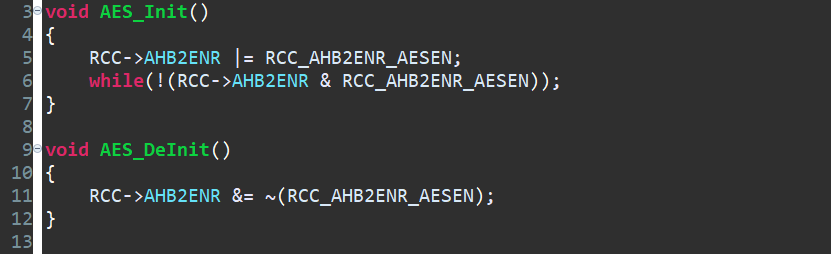
Since the AES Hardware Accelerator is on the AHB2 Bus and no special clock is required, we can just enable the peripheral by enabling the AESEN bit in the RCC_AHB2ENR register. Then wait for the AESEN bit to be set.
Input Encryption/Decryption Key

In all the encryption and decryption operations, the user can opt for either a 128-bit key or a 256-bit key. According to the Key size, we can set the KEYSIZE bit in the AES_CR register. First, we will take the array with the input data and traverse through it to determine it's size. Then, divide that value by 16 to determine the number of blocks. This driver is developed on the assumption that the length of the input data is a multiple of 128 bits or 16 bytes, and thus no padding is done. Hence the division by 16. Then, we will iterate through the Key array to determine it's size and then make a copy of it.

The AES Hardware Accelerator has 8 Key registers from AES_KEYR0 to AES_KEYR7. If we use a 128-bit key, we have to write the key array to the first four key registers ( AES_KEYRx [x = 0 to 3] ). If we use a 256-bit key, then we will have to write the key array to all the eight registers. In this function, we will take the Key array and it's size as arguments. Inside the for loop, we will load the first 4 bytes of the Key to a temporary 32-bit integer. Then, we will write it into the corresponding AES_KEYRx register.
Input Initialization Vector

In the AES Encryption and Decryption Operations, the Initialization Vector is used in the CBC and CTR Chaining Modes. We should write the Initialization Vector into the AES_IVRx (x = 0 to 3 ) registers. But, there's another perspective. In the CBC Mode, we will write the Least Significant Word of the IV to the AES_IVR0 register and the Most Significant Word to the AES_IVR3 register. But in CTR mode, the reverse should be done, that is, the Most Significant Word of the IV to the AES_IVR0 register and the Least Significant Word of the IV to the AES_IVR3 register.
Write Data to Data Input Registers

Since one block is only 128 bits long, we will take the Input array as an argument. Then, we will convert the 4 bytes of data into a 32-bit integer and copy it into a temporary 32-bit integer. Then, write it into the AES_DINR register according to the word position.
Read Data from Data Output Registers

For reading the encrypted data from the AES_DOUTR registers, we will traverse through the Output Array and then store the corresponding word from the AES_DOUTR register in the Output array.
AES Encryption in Electronic Codebook Mode
AES Encryption in ECB (Electronic Codebook) mode is a symmetric encryption process where the plaintext is divided into blocks, and each block is encrypted separately. This means that identical plaintext blocks will always produce identical ciphertext blocks. The main advantage of ECB mode is its simplicity, but it is not suitable for encrypting large amounts of data. The steps for AES Encryption in ECB Mode are
- Disable AES Peripheral
- Set the Operating Mode to Encryption Mode
- Set the Chaining Mode to ECB
- Set the Key size to 128-bit or 256-bit Key
- Write the Encryption Key
- Enable AES Peripheral
- Write Data to the AES Core
- Wait for the CCF bit to be set
- Read Data from the AES Core
- Clear the CCFC Flag
- Print the Encrypted Data to Terminal
- Repeat steps 7 to 11 until Input Data is completely encrypted
If we want to decrypt using the AES ECB Mode, we have to first do a Key Derivation Operation by setting the Operating Mode to Key Derivation and Write the Key into the AES_KEYRx registers. Then, set the Operating Mode to Decryption and proceed in a similar way to that of Encryption.
AES Decryption in Cipher Block Chaining Mode
In Cipher Block Chaining mode, each plaintext block is XORed with the previous ciphertext block before encryption, which helps eliminate patterns in the plaintext and ensures that identical plaintext blocks produce different ciphertext blocks. CBC mode is more secure than ECB mode because it eliminates patterns in the plaintext, but CBC mode requires the use of an Initialization Vector. The steps for AES Decryption in CBC Mode are
- Disable AES Peripheral
- Set the Operating Mode to Key Derivation
- Set the Key size to 128-bit or 256-bit Key
- Write the Decryption Key
- Write the Initialization Vector
- Enable AES Peripheral
- Wait for the CCF bit to be set
- Clear the CCFC Flag
- Set the Operating Mode to Decryption Mode
- Set the Chaining Mode to CBC
- Write the Initialization Vector
- Enable AES Peripheral
- Write Data to the AES Core
- Wait for the CCF bit to be set
- Read Data from the AES Core
- Clear the CCFC Flag
- Print the Encrypted Data to Terminal
- Repeat steps 13 to 17 until Input Data is completely encrypted
If you want to encrypt using the AES CBC Mode, there is no need of the Key Derivation process. You could just set the Operating Mode to Encryption, Write the Key and IV and follow a similar process to that of ECB Mode Encryption.
AES Encryption/Decryption in Counter Mode
Counter mode turns a block cipher into a stream cipher. CTR mode generates a stream of key-dependent pseudo-random values that are XORed with the plaintext to produce the ciphertext. This mode is useful for parallelization and random access to encrypted data and provides a high level of security when used properly with a unique IV for each encryption operation. The steps for AES Encryption/Decryption in CTR Mode are
- Disable AES Peripheral
- Set the Operating Mode to Encryption/Decryption Mode
- Set the Chaining Mode to CTR
- Set the Key size to 128-bit or 256-bit Key
- Write the Encryption/Decryption Key
- Write the Initialization Vector
- Enable AES Peripheral
- Write Data to the AES Core
- Wait for the CCF bit to be set
- Read Data from the AES Core
- Clear the CCFC Flag
- Print the Encrypted Data to Terminal
- Repeat steps 8 to 12 until Input Data is completely encrypted
There are no special steps involved in either Encryption or Decryption in Counter Mode of Chaining.
For generating the Initialization Vector, use the RNG Peripheral driver to create a 128-bit Random value in the application program. Note to input the Input array and the Key array as a string.


