Independent Watchdog | STM32F4 | IWDG | CMSIS
Independent Watchdog
The independent watchdog is based on a 12-bit downcounter and 8-bit prescaler. It is
clocked from an independent 32 kHz internal RC and as it operates independently from the
main clock, it can operate in Stop and Standby modes. It can be used either as a watchdog
to reset the device when a problem occurs or as a free-running timer for application timeout
management. It is hardware- or software-configurable through the option bytes(extracted from the Datasheet). Read the presentation on the IWDG peripheral by STMicroelectronics.

IWDG Registers
The Independent Watchdog has few registers. They are
- IWDG Key Register (IWDG_KR)
- IWDG Prescaler Register (IWDG_PR)
- IWDG Reload Register (IWDG_RLR)
- IWDG Status Register (IWDG_SR)
The Key register provides access protection to the Prescale Register and Reload Register. Writing 0x5555 to IWDG_KR enables write access to IWDG_PR and IWDG_RLR. Writing 0xAAAA loads the reload value stored in IWDG_RLR to the counter. Writing 0xCCCC enables the counter and starts downcounting. The Prescaler register allows us to scale the 32kHz internal RC Oscillator's clock to a maximum of 1/256. The Status register houses two bits to indicate the updation of the Reload and Prescaler registers.
Configuration
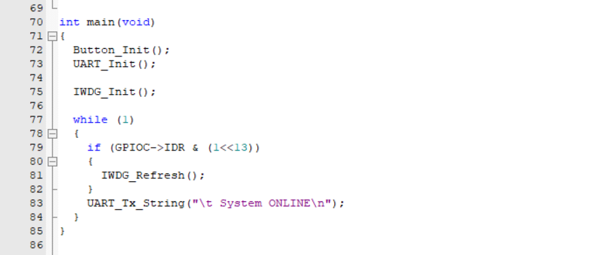
We will configure the IWDG peripheral to reset the microcontroller every 5 seconds it runs unless the USER BUTTON on the Nucleo-F401RE Development Board is pressed before the timeout. When the USER BUTTON is pressed, the counter is reloaded with the value stored in the reload register. To demonstrate that the device is running, a message will be printed on the Serial Terminal for every iteration of the while() loop, and when the counter is reloaded, another message is shown.
Walkthrough
Function Header and Definitions

Initially define the amount of time you want as the timeout. I have taken 5000 milliseconds. Then define function headers for Initializing and Refreshing the IWDG. Also, include function headers for initializing the User Button and UART.
Configuring Clock Source for IWDG
The IWDG Peripheral uses the LSI Oscillator as it's clock source. The LSI RC Oscillator runs at a frequency of 32 kHz. For that, we have to set the LSION bit in the RCC_CSR register and wait for LSIRDY bit to be set.
Initializing User Button

Since the USER BUTTON on the Nucleo-F401RE Development Board is connected to PC13 of the STM32F401RET6 microcontroller, we enable the clock to GPIOC on the AHB1 Bus. On reset, the Port C pins are in Input Mode, hence, there is no need to set that.
Initializing IWDG Peripheral

Enable write access to the Prescaler and Reload registers by writing 0x5555 to the Key Register (IWDG_KR). Then, choose the prescaler, here I have taken a division of 256. Then, calculate the value you want to reload the counter with.
Timeout = 5000 milliseconds
Frequency of LSI Oscillator = 32 kHz = 32000 Hz
Note that the Reload register takes a 12-bit value. Then, load the value in the Reload register to the counter by writing 0xAAAA in the Key Register (IWDG_KR). Finally, start the counter by writing 0xCCCC in the Key Register(IWDG_KR).
Reloading IWDG Counter

When the IWDG_Refresh() function is called, print a message on the Serial Terminal indicating the reloading. Then, write 0xAAAA to reload the IWDG counter.
Demonstration